Premise
I spent about a month on the Waturbine Aerodynamics team in February 2025. Waturbine is a design team at the University of Waterloo and subsidiary of Engineers Without Borders, looking to build sustainable, cost-effective small scale wind turbines with potential applications in powering low income households abroad, as well as competing in the International Small Wind Turbine contest.
Objective
They were looking for ways to export their wind turbine designs from QBlade, the industry standard wind turbine blade design software, and process it to make a mold for manufacturing. This was nontrivial due to two problems:
- The wind turbine blade surface is a continuous complex curve in 3 dimensions, so making a mold that had no undercuts or overhangs requires a complex curve surface to bisect the part (you can’t just pick some flat plane to split the blade), also known as the camber curve (similar concept to the camber line).
- The blade is not made of a single material, but is a lightweight foam core with a fiberglass composite on the surface. Thus, we’re not molding the entire blade, but the interior foam core; but we need to be sure that when the fiberglass composite is laid on the surface that the resulting shape is the intended turbine blade.
My objective was to:
- Make an internal offset of the blade that preserves its features, such that when fiberglass of a certain thickness is laid on top, we get the original turbine blade shape.
- Bisect the wind turbine blade along some continuous curved surface that leaves no undercuts, so that we have two halves of a mold.
Solution
1. Offset the blade by some fixed thickness
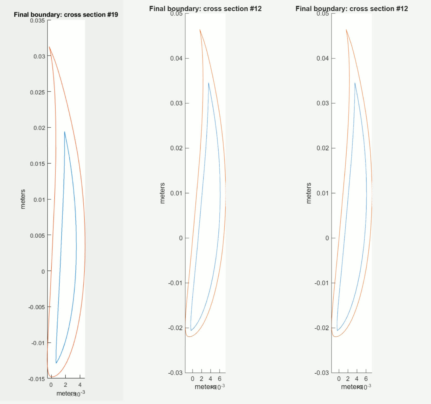
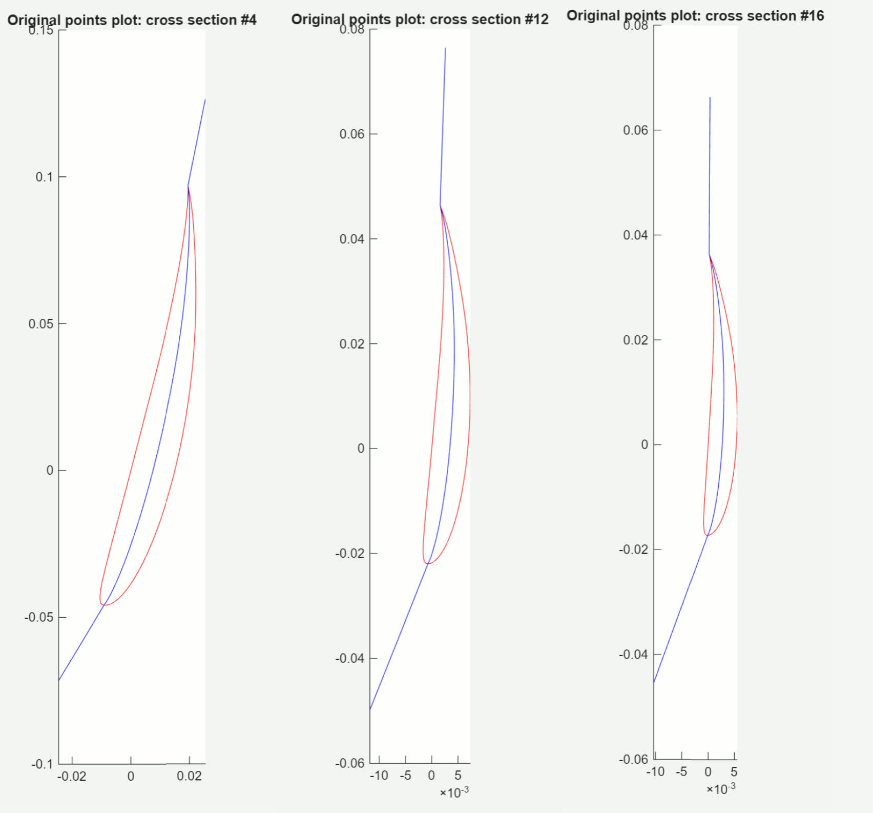
Below are some examples of the offset cross sections. Blue is the interior foam core, and red is the original shape - ideally, when we wrap the foam core with fiberglass, we will get the shape of the red outline (especially after bisecting it).
The algorithm I used to generate the blue shape is as follows:
- Fill the original shape with a grid of points, where each point is 0.025mm apart
- Generate a circle, and have it follow the perimeter of the red turbine outline. The circle’s radius is equal to the thickness of the fiberglass. As the circle travels along the perimeter, we delete all points that are inside of the circle.
- Fit some points to the perimeter of the resulting grid of points, which is the resulting blue outline.
2. Bisect the wind turbine blade
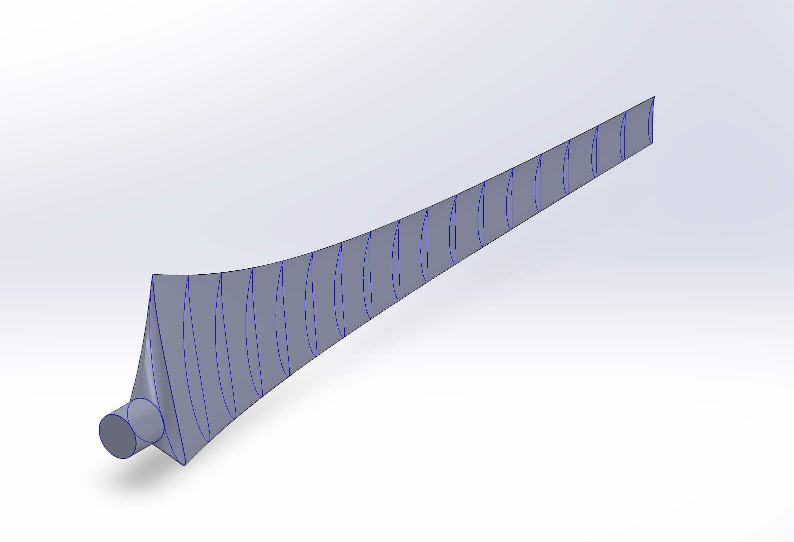
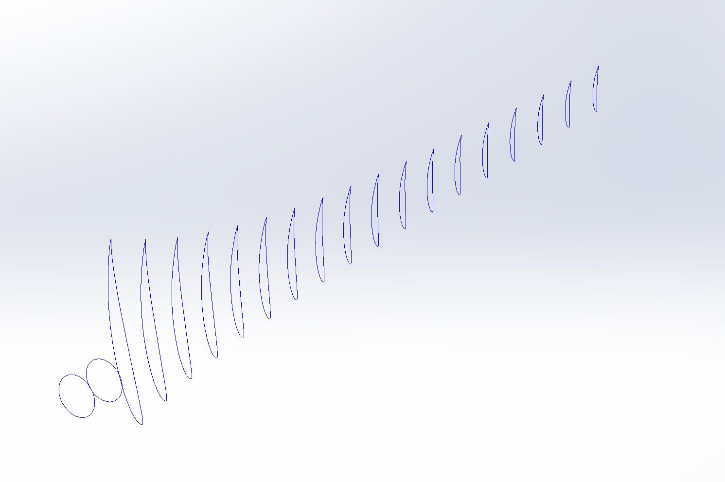
Similar to how the wind turbine blade shape is defined by a series of cross sections, we defined the camber surface as a series of cross sections that would later be reconstructed with a Boundary Surface.
For each cross section, we split it into a top and bottom half, then found the midpoint between points on the top and bottom surface curve to reconstruct the camber line of that cross section.
Below are some plots showing the camber line I generated for each cross section:
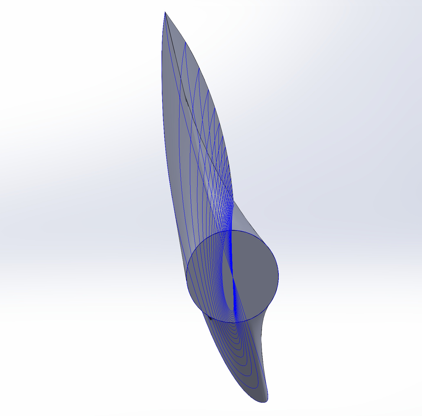
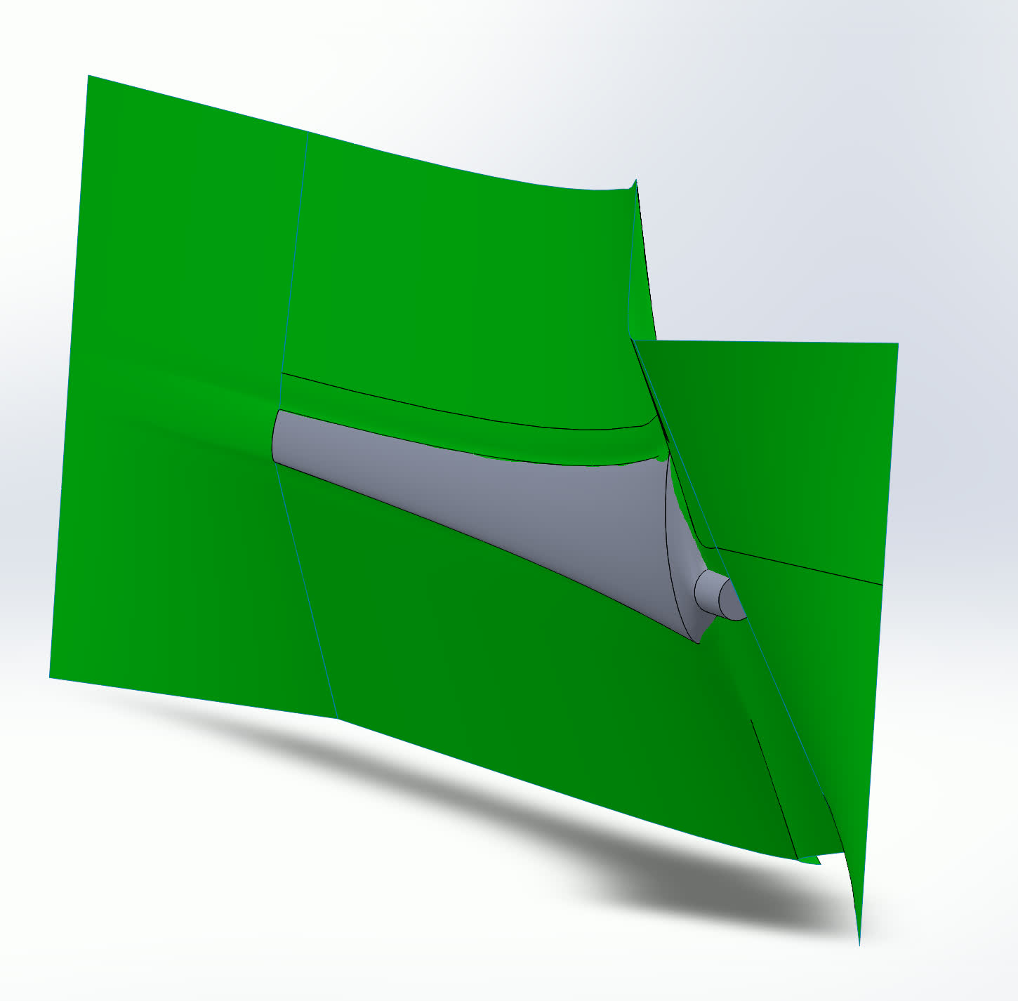
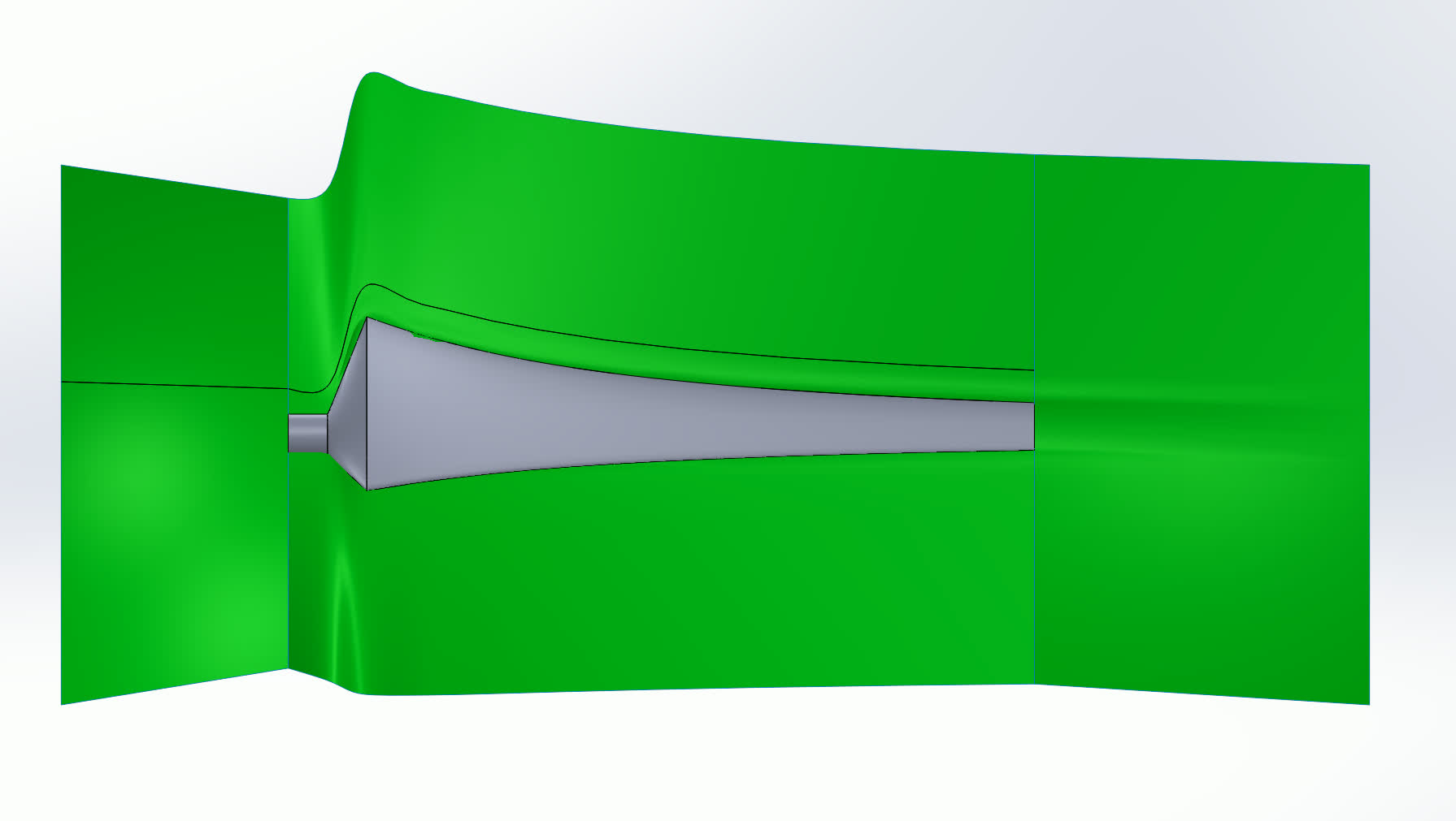
After combining the cross sections, the blade bisection plane looked something like the following:
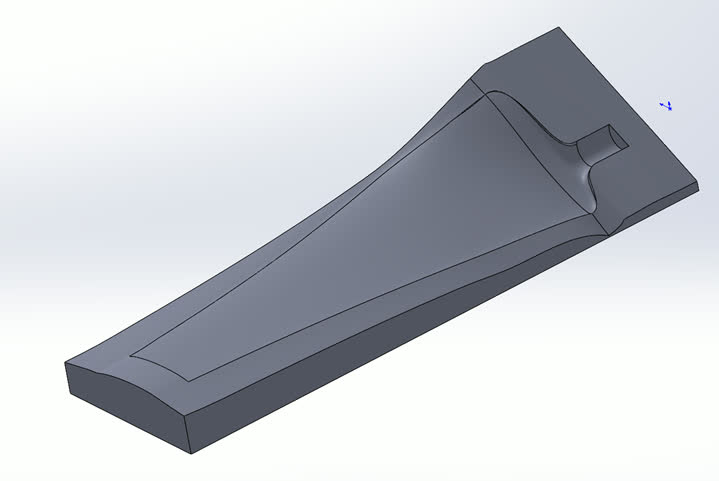

Extra photos
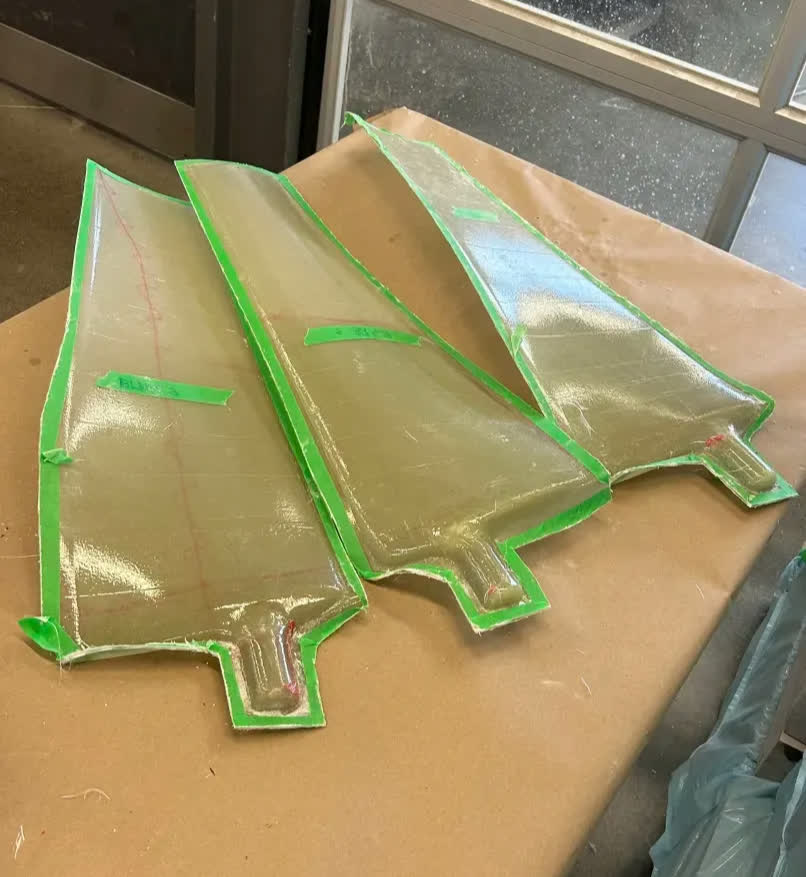
Fiberglass overlays that will go on top of the foam core, based on the generated molds